Lakeroadsters' Build Thread: '65 SWB Step

Discussion in '1960-1966' started by Lakeroadster, Mar 3, 2011.

  1. Lakeroadster

    Lakeroadster Member

    Joined:
    Jan 23, 2011
    Messages:
    1,599
    Location:
    Central Colorado
    Parking Brake Redeux Jan. 2010
    I removed the stock hand brake during the Camaro Dash installation and therefore needed to come up with a new location. Since I am running buckets seats I went with a floor mounted hand brake, low line style.

    Used a Lokar hand brake and then fabricated a spring return style linkage similar to the stock style but without the lever action. Relocated the rear cable attachment point from the side to the top of the trailing arms.

    The new set-up really works great!

    [​IMG]

    [​IMG]

    [​IMG]
     
    Last edited: Dec 9, 2012
  2. Lakeroadster

    Lakeroadster Member

    Joined:
    Jan 23, 2011
    Messages:
    1,599
    Location:
    Central Colorado
    The Grille March 2010
    On the Custom Classic Trucks website I saw a photo of stock grille with stainless bars (see the first picture below). Very clean... I want to replicate that look.

    First step was to cut out the stamped steel mesh. I used my air grinder and a 4" cut-off wheel.

    Next was fab'g. up some mounting brackets for both sides out of 1" angle. These were drilled for (5) 3/16" dia. stainless tubes.

    Next step is to make a mounting bracket for the center and then procure some stainless 3/16" tubing.

    [​IMG]

    [​IMG]

    [​IMG]
     
    Last edited: Dec 16, 2012
  3. Lakeroadster

    Lakeroadster Member

    Joined:
    Jan 23, 2011
    Messages:
    1,599
    Location:
    Central Colorado
    Grille Post #2 March 2010
    Spent some money on new headlight bezels and some 3/16" od. x 0.049 wall stainless tube for the grille bars. Made the center bracket to push out the tubes more at the top than at the bottom, thus following the grille original contour. Center bracket bolts to stock center grille support bar.

    Next step is to tap the o.d. of the tubing to allow bolting it to the brackets, which will put the tubes in tension and make everything pull tight and straight.

    Mocked everything up for a sneak preview of coming attractions.

    [​IMG]

    [​IMG]
     
    Last edited: Dec 9, 2012
  4. Lakeroadster

    Lakeroadster Member

    Joined:
    Jan 23, 2011
    Messages:
    1,599
    Location:
    Central Colorado
    Grille Post #3 March 2010
    I ended up having a coworker die cutting 10-32 threads on the o.d. of the tubes on one end and TIG weld flat washers to the other end.

    Here is the finished product, ended up pretty much like I had hoped.

    [​IMG]

    [​IMG]
     
    Last edited: May 29, 2014
  5. Lakeroadster

    Lakeroadster Member

    Joined:
    Jan 23, 2011
    Messages:
    1,599
    Location:
    Central Colorado
    Steering Column Post #1 April 2010
    I am planning to install a walnut grip steering wheel, should look "period correct" with the Camaro dash. The existing steering wheel has some slop in it so I investigated. The PO had butchered up the upper steering column bonnet and the upper bearing was loose, with 2 screws holding it in place instead of the 3 it is designed to have retain it. What is the deal with PO's???

    Ok, so I called Tony Smith (Tony Smith, 4-5-6 Chevy Trucks, 560 South 11th Street, Kansas City, KS 66105
    913-207-7789 4-5-6chevytrucks@sbcglobal.net) and after some discussion bought a replacement upper bonnet and a secondary bonnet to remove the old 3-speed shifter mounting boss. That way the steering column will look correct since the truck now has a 4-speed floor shifter.

    So I gut the upper part of the column to replace all the new pieces I got from Tony. I then noticed the steering shaft was still very loose, which I had assumed all along was because of the upper bearing.

    I pop the hood on the truck and grab the steering shaft where it exits the steering column. The bottom bearing is, well, no longer holding the shaft.

    I again called Tony and he talked me through the sequence of events to pull out the entire column. He also said to look at the steering shaft, that sometimes the shaft becomes severely worn if the lower bearing fails.

    Here is a synopsis of how I removed the column which was really pretty much straightforward deal.
    -Remove the driver’s side front tire
    -Via the front drivers side wheel well remove the sheet metal cover that shrouds the steering shaft (held on with sheet metal screws),
    -Spray some penetrating oil on the steering box input shaft rag joint spline,​
    In Cab
    -Remove the steering wheel (you will need a steering wheel puller)
    -Unplug the steering column wiring harness (2 Plugs located under the dash),
    -Remove the upper bearing / turn signal switch. [(3) retaining screws],
    -Remove the sheet metal cover inside the cab where the column goes through the firewall (4 sheet metal screws)​
    Under-hood:
    -Remove the transmission shift linkage from the column,
    -Remove the (1) lag bolt holding the column to its bracket on the firewall,
    -Remove the (3) bolts that hold the firewall bracket to the firewall,
    -Unbolt the rag joint from the steering box [(1) bolt] (you may need a pickle fork ball joint separator or similar device for this, mine slid right off)​
    In-Cab
    -Remove the (2) bolts that hold the column to its dash support bracket,
    -Un-plug the brake light switch,
    -Remove the 4 bolts that hold the dash support bracket to the dash.
    Now remove the column, you will need to rotate it so the transmission shifting arms are in the correct orientation to make it through the tear drop shaped opening in the firewall.​

    I let the column slide up and off the steering shaft. Once the column was out then I removed the steering shaft from the front driver’s side wheel well.

    Inspect the steering shaft for wear. It may need to be welded up and machined back down if it is worn, or get a replacement from somebody like Tony Smith.

    Remove the lower bearing from the column by removing the (2) bolts that hold the retainer to the column.

    Re-assemble by reversing the order.

    Note that the lower bearing was originally a ball bearing. Some aftermarket bearings are a brass sleeve type bearing. I speculate this is because the original ball bearing design was weak? Also this lower bearing gets road grime and crud into it via the opening in the lower column for the shifter linkage. Probably why the lower bearings wear out and ultimately fail.
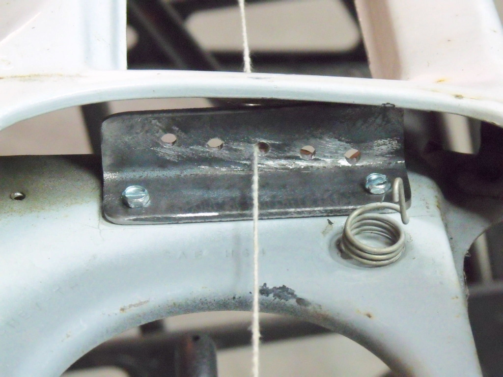
    Following Tony's advice I had the column out in about half an hour. Sure enough all the rollers in the bearings were gone and the shaft was cut / worn due to rubbing on the bearing outer race (see picture below). The 3/4" thick shaft was now 1/2" diameter! Now that is a dramatic change 'cause from a strength factor the 1/2" shaft is only 20% as strong as the 3/4" shaft!

    While I had the column out I used my die grinder and a cut-off wheel to remove the old 3-speed shifter linkage at the bottom of the column.

    I consider myself quite lucky:
    Lucky that we have people like Tony Smith to be there to give advice and lucky that I found this problem when the truck was sitting in my shop, instead of when I was buzzing up the highway in traffic.
    I ordered a new bearing and took the shaft to work. I am also lucky to have worked at fab. shops over the years so if I need something like this fixed by "real" welders and machinists I have access to them. And these guys seem to get a real kick out of helping on my old projects. Great guys..... So we set up a welding positioner at the shop and George "the welder" did the welding using tig. Then "machinist" Mark chucked the shaft in his lathe and we used the cross slide to straighten the shaft, which was bent about 3/4". Once we got it straight he machined the weld down. Looked factory fresh after the repair...... now I am just waiting for the bearing to show up so I can begin re-assembly.​

    More on this later....

    [​IMG]

    [​IMG]

    [​IMG]

    [​IMG]

    The Repaired Column, 4105 PSI Principal Stress
    [​IMG]

    The Worn Column, 15810 PSI Principal Stress
    [​IMG]
     
    Last edited: Feb 11, 2014
  6. Lakeroadster

    Lakeroadster Member

    Joined:
    Jan 23, 2011
    Messages:
    1,599
    Location:
    Central Colorado
    Steering Column Post #2 April 2010
    Reinstall of the column was pretty much straight forward. Only Problem I had was getting the intermediate bonnet (the one that now does not have the three speed shifter arm bracket) slid over the column inner shaft. The keyway kept getting hung up. So I filed and filed and filed and filed. Eventually everything lined up.

    I also added a Grant #992 steering wheel. I wanted a walnut wheel with actual finger grips on the back, and a wheel that is strong enough for a truck that has "arm strong" steering. This one is 15" in diameter x 2-3/4" dish and comes with a built in horn button. Not the cheapo-cheesy mushroom type that just snaps into place.

    This is a strong heavy duty steering wheel, worthy of our trucks. I know many of the walnut type wheels are delicate and spindly, not the case with this one.

    The new steering wheel has about 3 inches less dish than the previous one. I can now move the seat forward and recline the seat a bit. Much better.

    [​IMG]

    [​IMG]
     
    Last edited: Dec 9, 2012
  7. Lakeroadster

    Lakeroadster Member

    Joined:
    Jan 23, 2011
    Messages:
    1,599
    Location:
    Central Colorado
    Console Post #1 July 2010
    Sniped a genuine GM 1976 Blazer console off EBay, no cracks and very restorable. A classic case of don't judge a book by its cover. Lucky for me the seller answered my questions as to if the console was cracked or damaged, and he answered it honestly. (You just never know who you are dealing with on EBay)

    The console fits in my '65 C10 like it was meant to be. All I will need to do is install some mounting brackets to get it to the optimum height. (I am 'diggin the little Chevy emblem too)

    Let the console resto begin!

    [​IMG]


    Disassembled the console. I was surprised at how well these are built and that I still haven't found any cracks. The only noticeable wear is from the seat belts rubbing against the sides made a scuffed area.

    The console is made from some sort of plastic material. Once the upper and lower halves are unbolted they separate and give access to the upper half where there are tabs that need to be bent to remove the chrome strip that surrounds the lid.

    I used Rustoleum Aircraft stripper in a rattle can to remove the blue paint from the outside surfaces (the raw plastic is black in color). Then the chrome pieces were polished up using some fine steel wool and WD-40, followed by some good old paste wax.

    The only things I think I will replace are the 10-32 fasteners. They are rusty and I will probably replace them with stainless.

    Next step is to make a mounting bracket to adapt the console to the 65 truck floor. Then the console will be ready for paint.... but I need to pick a color first.

    [​IMG]

    [​IMG]

    [​IMG]

    [​IMG]
     
    Last edited: Dec 9, 2012
  8. Lakeroadster

    Lakeroadster Member

    Joined:
    Jan 23, 2011
    Messages:
    1,599
    Location:
    Central Colorado
    Console Post #3 July 2010
    I fabricated brackets to mate the console to the '65 floor pan. Basically just used 3/16 x 1 flat bar bent to raise the console and bent to fit the slope of the floor. Then drilled holes to bolt to the console and to the floor.

    Interior repaint scheme will be:
    Black console.
    Fawn doors with black bolted panels.
    Fawn dash with black gauge panels.
    Gray dash pad cover.
    Black Seats,
    Black Carpet.

    [​IMG]

    [​IMG]

    [​IMG]

    [​IMG]
     
    Last edited: May 29, 2014
  9. Lakeroadster

    Lakeroadster Member

    Joined:
    Jan 23, 2011
    Messages:
    1,599
    Location:
    Central Colorado
    Radiusing The Rear Bed Rails, Post #1
    I saw this idea and decided to give it a try. I am using long radius 1-1/2" pipe elbows.

    The radius looks good 'cause it is visually similar to the fender radius. Look at the last photo below, see how the roof radius, fender radius and now the bed rail radius all look similar... makes it look like something GM should have done, back in the day, IMHO.

    [​IMG]

    [​IMG]

    [​IMG]

    [​IMG]

    [​IMG]

    [​IMG]
     
    Last edited: Feb 4, 2014
  10. Lakeroadster

    Lakeroadster Member

    Joined:
    Jan 23, 2011
    Messages:
    1,599
    Location:
    Central Colorado
    Rear Cab Air Vents, Sept 2010
    Wanting to get better fresh ventilation flow through in the cab I began by looking at newer truck cabs to see how they are made. I noticed that Dodge is putting (2) air vents in the rear wall of the cabs.

    Sales Brochure Description:
    A truck cab ventilation system and method which includes an air exhaust at the rear of the cab. An inlet vent in the front of the cab (kick panel vent) produces a positive pressure within the cab which causes flow-through ventilation air flow from the front to the rear of the cab when the truck is moving. . The exhaust vent includes flexible elastomeric louvers which are held by gravity in a closed position and are moved into an open position when air flows out through the exhaust system.

    I purchased a couple of used vents off a 03-08 Dodge Ram Truck and then made a concept of the installation on cad.

    Attached photos show the concept and the fabricated parts.

    [​IMG]

    [​IMG]

    [​IMG]
     
    Last edited: Dec 9, 2012
  11. Lakeroadster

    Lakeroadster Member

    Joined:
    Jan 23, 2011
    Messages:
    1,599
    Location:
    Central Colorado
    Rear Cab Air Vents, Post #2: Sept. 2010
    The openings were cut undersize such that flanges were formed. Then the vent panel surround is bolted to the cab.

    Next step is to primer and paint the surrounds, install them and then seam seal the gaps.

    [​IMG]

    [​IMG]

    [​IMG]

    [​IMG]
     
    Last edited: Dec 9, 2012
  12. Lakeroadster

    Lakeroadster Member

    Joined:
    Jan 23, 2011
    Messages:
    1,599
    Location:
    Central Colorado
    Tail Pipe Post #1 Sept. 2010
    Finally getting around to running tail pipes off the glass-pack mufflers. Always the one for trying something different I am running the tail pipes on the outside of the frame rail. Why you ask? Well I have a rear frame mount tank and running the tail pipes outside the frame also keeps them away from the rear suspension swing arms.

    I had a set of 64-74 GM A-Body tailpipes and decided to use them as the starting point.

    So using my trusty Sawsall and some duct tape (temporary extra set of hands) I have the route pretty much mocked up. Next step is to buy some straight 2-1/2" pipe and then figure out the exhaust exit at the rear of the truck, but that should be pretty easy. Then clean all the joints and tig / mig weld everything up. See Post #128 for the finished product.

    [​IMG]

    [​IMG]
     
    Last edited: Mar 4, 2014
  13. Lakeroadster

    Lakeroadster Member

    Joined:
    Jan 23, 2011
    Messages:
    1,599
    Location:
    Central Colorado
    Tail Pipe Post #2, Sept. 2010
    Done. I ended up cutting the exhaust off nearly flush with the roll pan, I didn't want the tips to stick down since everything looks smooth across the back.

    Pretty stoked with the way it sounds too, here is a video clip


    YouTube - Lakeroadster's 1965 Chevrolet C10 SWB Step Side

    [​IMG]

    [​IMG]

    [​IMG]

    [​IMG]

    [​IMG]

    [​IMG]

    [​IMG]
     
    Last edited: Feb 4, 2014
  14. Lakeroadster

    Lakeroadster Member

    Joined:
    Jan 23, 2011
    Messages:
    1,599
    Location:
    Central Colorado
    Bed Floor Wood, Post #1 Sept 2010
    As previously discussed I am using (2) pieces of 3/4" pressure treated plywood for the bed floor. Functionality on a budget and not beauty is the goal here. The center seam is covered by a stainless bed strip and the wood is attached to the bed around the perimeter with carriage head bolts.

    So far so good. Next step is installing the cross sills, drilling holes for the bed to frame fasteners, then disassembly, paint the steel parts, seal the wood and reassemble.

    [​IMG]

    [​IMG]
     
    Last edited: Dec 9, 2012
  15. Lakeroadster

    Lakeroadster Member

    Joined:
    Jan 23, 2011
    Messages:
    1,599
    Location:
    Central Colorado
    Bed Floor Wood, Post #2, Oct. 2010
    Used Thompsons Waterseal to seal all the plywood and painted all the bed angles and other surfaces that contact the wood.

    Cut wood for the wheel tubs and fabricated supporting steel inside the wheel tubs for the wood.

    I have a heavy rubber bed mat that will be cut to fit the bed and will be used whenever hauling anything.

    All in all this project turned out pretty much as planned.

    [​IMG]

    [​IMG]

    [​IMG]
     
    Last edited: Dec 9, 2012
  16. Lakeroadster

    Lakeroadster Member

    Joined:
    Jan 23, 2011
    Messages:
    1,599
    Location:
    Central Colorado
    Casters and Concepts, Oct. 2010
    Fabricated some caster support brackets for my step side bed. This allows positioning the bed without using my engine hoist.

    Makes moving it in and out of my work bay much easier.

    Going to strip paint and try man hand at doing "Patina". Thinking Hugger Orange body with white cab, but as a worn out old speed shop truck. If I don't like it I can always strip it back down.

    The look I am shooting for is a "shop truck" for the fictional company "Hot Rod Fabricators". Plan is to paint the logo on the door, along with some lettering on the rear fenders that say "Speed Shop". Something similar to the photos shown below but in the color combo I mentioned above. Should be interesting.

    [​IMG]

    [​IMG]
     
    Last edited: Feb 4, 2014
  17. Lakeroadster

    Lakeroadster Member

    Joined:
    Jan 23, 2011
    Messages:
    1,599
    Location:
    Central Colorado
    Striping the Step Side Bed Oct. 2010
    Well, just finished up 2-1/2 days worth of effort stripping the rear fenders and bed. I used a Norton Rapid Strip wheel on my 4-1/2" angle grinder. They are great; if you haven't tried these you owe it to yourself to give them a try.

    Man what a dirty job! I must say I am diggin' the look in bare steel though. I have a half a notion to just wipe it down with Gibbs and say Done! http://www.roadsters.com/gibbs/

    To be honest the mess and expense of primering and painting has me questioning my sanity, especially heading into winter here in Colorado.

    Good news is where I live (Eastern Plains of Colorado) it is a semi-arid climate; I have raw steel in my shop that has been setting for 5 years with no rust on it!

    [​IMG]

    [​IMG]
     
    Last edited: Dec 9, 2012
  18. Lakeroadster

    Lakeroadster Member

    Joined:
    Jan 23, 2011
    Messages:
    1,599
    Location:
    Central Colorado
    Rear Stake Pockets, Oct. 2010
    Finally got around to repairing the butchered up rear stake pockets. I had to make some 1-1/2 x 2 tubing out of 2 x 2 tubing. Then cut the opening and welded them in.

    They will need some filler, but came out pretty good.

    [​IMG]
     
    Last edited: Dec 9, 2012
  19. Lakeroadster

    Lakeroadster Member

    Joined:
    Jan 23, 2011
    Messages:
    1,599
    Location:
    Central Colorado
    Roll Pan, Oct. 2010
    Added license plate lights to the roll pan (O’Reilley Auto Parts el cheapo's). These should not be very visible with the roll pan installed on the bed. But Johnny Law will appreciate it, I am sure.

    [​IMG]

    [​IMG]
     
    Last edited: Dec 9, 2012
  20. Lakeroadster

    Lakeroadster Member

    Joined:
    Jan 23, 2011
    Messages:
    1,599
    Location:
    Central Colorado
    Bed Mat Nov. 2010
    I cut down a full size long bed rubber bed mat to fit my widened mini-tubbed short bed. The mat is about 1/4 inch thick and is very heavy.

    [​IMG]
     
    Last edited: Dec 9, 2012

Share This Page