• We have upgraded our forum software! See here for details.

Remove Tank and Dis Brakes

Looking Good !

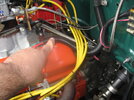
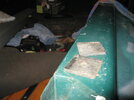
Remember : fuel filter goes between the fuel pump and the carby , never , EVER under the bed/cab nor before the fuel pump ! .

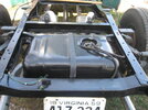
Good luck selling that original tankl , I tried to *give* one away for almost a decade before tossing it in the scrap pile .

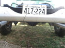
I look at pic. # 1 and shiver ~ I don't miss the snow atall .
 
Been a long time back up and Running

Well been busy with all kinds of winter stuff, and had a chance to start back on the gas tank installation, hooked up the fuel hose, the red AN connection near the break drum is where the hose ended once removed from inside the cab. Added three extra feet and presto connected. Also install plugs on all of the other port, return lines pressure lines etc. These will come in handy if fuel injection is installed later.

I also completed the electrical connection. The fuel ground and fuel sending unit wires were extended. I like the weather tight connections, (GM style).
The fuel sending unit provides accurate readings. I modiflyed the unit to work with the originial dash gage. (see earlyer post)

The hole in the cab near the door will need to be patch. Looking from th rear the profile of the new CJ7 jeep tank is above the rear differenal, thats cool.
Since posting this; the bed has been placed back on the frame and I will provide pictures of how the filler hole is located at the tank and clears the frame and underside of the bed., I think it will work great. Clearance for wires, hoses and everything is great no issues.
 

Attachments

  • IMG_3888.jpg
    IMG_3888.jpg
    125.1 KB · Views: 482
  • IMG_3889.jpg
    IMG_3889.jpg
    114 KB · Views: 503
  • IMG_3890.jpg
    IMG_3890.jpg
    109.7 KB · Views: 503
  • IMG_3892.jpg
    IMG_3892.jpg
    101.5 KB · Views: 495
  • IMG_3893.jpg
    IMG_3893.jpg
    121.2 KB · Views: 567
Last edited:
Little Mod

Placement of the short bed back on the frame, nothing associated with the gas tank mod interfered with the bed, however instead of the 1/4 in insolation pads, I went with a 3/4 inch equipment insulator.
The side view shows the height difference barely noticeable, also I may move the bed back approximately one inch so the large 16 inch tiles I have will clear the cab corner. Right now it rubs up against the cab when set at stock location.
 

Attachments

  • this may be the spot.jpg
    this may be the spot.jpg
    92.3 KB · Views: 505
  • out with the old.jpg
    out with the old.jpg
    84.6 KB · Views: 529
  • no clearance issues.jpg
    no clearance issues.jpg
    58 KB · Views: 463
  • little highter.jpg
    little highter.jpg
    89.9 KB · Views: 464
  • pad.jpg
    pad.jpg
    10 KB · Views: 488
Back to Bed

Well, placed the bed back on the chassis with the 3/4 inch spacers rasing it just slightly higher, can't really notice. Also looking from the back you can see the relocated cross member just behind the license plate. It's also turned upside down, (see Nate had to invent something). This week will see about getting a one inch tube bent for the fuel filler tube connection. I am still hesitant about drilling a two and a quarter inch hole in a perfectly good fender for the filler cap, but running out of good options.
Also the bed in not bolted down just yet, it's sitting about an inch further from the cab, this will allow the use of side spare tire (large 16 inch) without rubbing the cab.
 

Attachments

  • IMG_3907.jpg
    IMG_3907.jpg
    126.1 KB · Views: 503
  • IMG_3908.jpg
    IMG_3908.jpg
    74 KB · Views: 483
Last edited:
Looking Good !

I'm no fan of fender fuel filfers , I've had & seen too many get ripped right off when a tire blew :eek: .

Can't you have it come up behind the fender & before the rear bumper ? .
 
Little Different

Well, been away for a while, and located my filler and cap. Most will not like the location, however it places the cap tube directly over the tank inlet tube. About 18 inches of tube was needed and tight against the bed side within the pontoon fender.
 

Attachments

  • 003.jpg
    003.jpg
    89.4 KB · Views: 414
  • 002.jpg
    002.jpg
    88 KB · Views: 508
Relocated Fuel Filler

That's actually pretty good ! .

Most just go the lazy way and place it in the bed where you cannot access it if there's anything in the bed and , it'll spit fuel and fumes as you're filling up and this ruins the highly finished wood....

Your idea is well thought out .

Keep up the good works and pictures please .
 
Plug the Hole

Not much of a welder (but once spend overnight at a super eight motel) my Craftsman mig is over 20 years old had to replace the inside feed tube was rusted out, looks like a bike brake cable and the welding wire is fed thru the center when the trigger is pulled. The steel section removed from the bed was used for the plug, Needed to be bent to match the body contours. weld grind weld grind.
 

Attachments

  • 011.jpg
    011.jpg
    116.3 KB · Views: 453
  • 010.jpg
    010.jpg
    77.9 KB · Views: 476
  • 008.jpg
    008.jpg
    79.3 KB · Views: 500
  • 003.jpg
    003.jpg
    74.3 KB · Views: 463
  • 005.jpg
    005.jpg
    87.9 KB · Views: 501
  • 015.jpg
    015.jpg
    75.3 KB · Views: 497
Last edited:
Plug that hole

First sanding and primer. I did used some of that red steel auto body putty. Need to work on the low and high points.
 

Attachments

  • 002.jpg
    002.jpg
    62.1 KB · Views: 484
  • 003.jpg
    003.jpg
    50.1 KB · Views: 469
LUV that red stuff

Looks fine to me. This concludes my fuel tank relocation, now to the front brakes.. hand me the discs please!
 

Attachments

  • 003.jpg
    003.jpg
    57 KB · Views: 491
  • 001.jpg
    001.jpg
    96.9 KB · Views: 435
First Day Brakes

Today, I took the drums off and separated the hubs from the drums, grinding out the three pins holding everything together.
 

Attachments

  • first dat brakes 004.jpg
    first dat brakes 004.jpg
    144.1 KB · Views: 455
  • first dat brakes 003.jpg
    first dat brakes 003.jpg
    150.6 KB · Views: 472
  • first dat brakes 002.jpg
    first dat brakes 002.jpg
    91.9 KB · Views: 486
  • first dat brakes 001.jpg
    first dat brakes 001.jpg
    154 KB · Views: 483
  • first dat brakes 005.jpg
    first dat brakes 005.jpg
    134.1 KB · Views: 450
  • first dat brakes 006.jpg
    first dat brakes 006.jpg
    132.9 KB · Views: 467
  • tire.jpg
    tire.jpg
    111.1 KB · Views: 483
Day Two

Removed the dust shield by drilling out the rivets, baring's fell out and I drove the races out with a large punch. Clean up everything, Will be packing tonight. :D

The rotors are from a C-10, so was the first year for GM trucks 1974?:o
 

Attachments

  • day two 003.jpg
    day two 003.jpg
    111.9 KB · Views: 450
  • day two 004.jpg
    day two 004.jpg
    121.2 KB · Views: 442
  • day two 002.jpg
    day two 002.jpg
    70.9 KB · Views: 458
  • day two 001.jpg
    day two 001.jpg
    128.9 KB · Views: 430
Moving foward

I assembled the hub to the rotors and installed the Barings. Installed the new bracket on the spindle. New parts on an old truck so cool, also I added pictures of my two best friends for today, Pene and Punch
 

Attachments

  • three 002.jpg
    three 002.jpg
    124.9 KB · Views: 451
  • three 003.jpg
    three 003.jpg
    121.3 KB · Views: 398
  • three 006.jpg
    three 006.jpg
    115.1 KB · Views: 465
  • three 005.jpg
    three 005.jpg
    124.4 KB · Views: 485
  • three 004.jpg
    three 004.jpg
    148.3 KB · Views: 424
Installed rotor

This look nice, and the C-10 rotor and disc should stop this 3100, next the master cylinder under the floor.

I will soon find out if my stock 16 inch tires ( rims) fix over that C-10 stuff.
 

Attachments

  • tire.jpg
    tire.jpg
    111.1 KB · Views: 445
  • first dat brakes 005.jpg
    first dat brakes 005.jpg
    134.1 KB · Views: 480
  • installed dics 001.jpg
    installed dics 001.jpg
    118.1 KB · Views: 489
Moving on

The rotors and hubs are attached, I had the special pins holding the calipers on backwards. The stock 16 inch wheels do not fit so a 1/4 inch spacer has been ordered. No new rims for this old Chevy.

I removed the stock master cylinder and installed the new bracket.
 

Attachments

  • front comp 001.jpg
    front comp 001.jpg
    104.2 KB · Views: 423
  • front comp 002.jpg
    front comp 002.jpg
    113 KB · Views: 452
  • front comp 003.jpg
    front comp 003.jpg
    136.5 KB · Views: 418
master installed

spent about an hour on my back installing the master cylinder, follow instructions workout well, need to remove my cross member supporting my transmission and then reinstalled. original brake paddle attached, inside height is fine. Will need to run new brake lines and bleed. Picture are not the greatest but you get the gist. ;)
 

Attachments

  • master install 002.jpg
    master install 002.jpg
    96.1 KB · Views: 448
  • master install 001.jpg
    master install 001.jpg
    108 KB · Views: 436
Plumbing Completed

Here is where this project is now. Completing the plumbing and new connections,

The first picture is the braded 3/8 vacuum line from the intake to the new master cylinder. The second picture is the vacuum running down the fire wall using existing firewall clips. I used the manifold port due to the carburetor will be changed out in the near future with some fuel injection system.

Picture 3 and 4 are showing the MC install and the blot connections to the frame rail. I tucked the angle brace inside the frame and bolted it to the frame vs. bolting to the bottom of the frame. The square tube is my transmission cross member for my 200R4 (1987) overdrive trans.

Picture 5 and 6 are the proportion valve to the rear drums (10lbs) and my blue bed frame 3/4 inch cushion.

Picture 7.8 and 9 are the rear lights installed once again, the front disc from underneath and the filler bottle they give to fill the hard to reach MC. I ordered a remote reservoir.

I ordered new rear cylinder and will be replacing them this weekend. Notice the dog in the last picture lower left, this guy is with me all the way, he's a cocker and very smart.
 

Attachments

  • plumbing 001.jpg
    plumbing 001.jpg
    126 KB · Views: 440
  • plumbing 002.jpg
    plumbing 002.jpg
    108.3 KB · Views: 455
  • plumbing 004.jpg
    plumbing 004.jpg
    117.8 KB · Views: 438
  • plumbing 008.jpg
    plumbing 008.jpg
    126 KB · Views: 446
  • plumbing 003.jpg
    plumbing 003.jpg
    169 KB · Views: 471
  • plumbing 005.jpg
    plumbing 005.jpg
    186.6 KB · Views: 457
  • plumbing 011.jpg
    plumbing 011.jpg
    115.8 KB · Views: 432
  • plumbing 009.jpg
    plumbing 009.jpg
    147.4 KB · Views: 415
  • plumbing 010.jpg
    plumbing 010.jpg
    121.1 KB · Views: 443
Last edited:
Remote fill

I installed a remote reservoir so I could check the fluid without laying on my back. Made a quick bracket, did not used the clear hose provided. and it's done. Brakes feel good will test drive tomorrow. Maybe even drive it to
church.
 

Attachments

  • remote 001.jpg
    remote 001.jpg
    108 KB · Views: 429
  • remote 002.jpg
    remote 002.jpg
    40.9 KB · Views: 425
  • remote 003.jpg
    remote 003.jpg
    50.6 KB · Views: 408
  • remote 004.jpg
    remote 004.jpg
    112.7 KB · Views: 427
  • remote 006.jpg
    remote 006.jpg
    141.8 KB · Views: 471
Back
Top