Bill Hanlon
Member
Decided that it was time to treat my 12 volt, negative ground, but otherwise mostly stock, 228 inch '52 GMC engine to a better ignition system. While the Pertronix system is simple to install (and ultimately less expensive) I have always been a fan of GM's HEI ignition. Especially when you need to get a replacement module 20 miles outside of Podunk TX. When DeadZoneTrucker brought Deve's solution to my attention, I decided to look into doing it Deve's way.
Before I started I spent some time on the phone with Deve talking about mounting alternatives for the module, as I didn't want to use his mounting bracket. Nice guy, willing to help. Here is a pointer to his kit:
High Energy Ignition Using Your Stock Distributor!
I hooked up an old ignition scope that a friend gave me years ago. It showed that I had a total of about 6 degrees of timing jitter using my stock points distributor.
My first thought was to mount the HEI module inside the cab, but I was concerned with the 3-4 feet long leads from the mag pickup. The mag pickup voltage levels are very low and could be susceptible to electrical noise, especially over such long wires. My solution was to use shielded, 22 gauge, twisted pair wire from the pickup to the module.
Bilbo came by one day a couple of weeks ago and we went to work. The plan was to do a temporary installation with longer than necessary wires to assure that there wouldn't be problems with the final installation. We installed the HEI module on the passenger's side inner fender under the hood. We used 10' of the twisted pair wire for the pickup to HEI module, figuring that if that long wire worked OK, the final solution of 3-4 feet would work as well. We also shielded the 14 gauge wire we ran between the coil negative and the module to keep it from generating electrical noise into the mag pickup wire. Both shields were grounded at the HEI's ground point. Bilbo (an electrician by trade) pointed out that the shields should only be grounded at one end.
My GMC distributor was the "short cap" variety which does not have enough room inside to mount the mag pickup. Deve provided a "tall cap" distributor for an additional $30. It arrived freshly cleaned, painted and lubed and seemed to be in very good condition. Later testing with the HEI module showed the timing jitter of this distributor to be around 2.5 degrees total.
I have around 6000 miles (2 years) on my current set of plug wires, so I decided keep them. Same with the AC R45 spark plugs (nice light tan color on the inside insulators), so I just re-gapped them from the stock 0.032" to 0.045" and put them back in. Cranked up the engine, timed it to the BB, and then advanced it about 1/2 way to the "A" mark on the "octane selector" on the distributor. This engine started quickly using the stock ignition and so far it still does on the HEI.
Drove the truck for a week and a half using the temporary HEI mounting with the long wires and all seemed well. Mileage on the only tank of gas was 15.37 MPG, mostly suburban driving, which is slightly better than my usual 14.5 to 15 MPG, but hardly a good comparison with just one tankful used.
Up to this point I'd pretty much followed Deve's instructions with the exception of longer, shielded wires. In the mean time, I'd gone back and re-read his article. One thing I noticed was his comment about hiding the module inside an old voltage regulator cover. I decided to hide my module inside a voltage regulator, mounted in the stock location on the firewall. While I was at it, I'd disguise the wiring as best I could to make it look stock.
I started by removing all parts from the frame of the voltage regulator. Then I re-attached all three connection points to the frame using pop rivets.
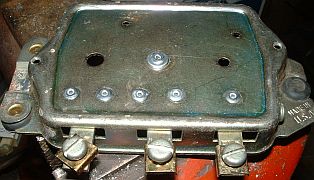
The connection points (BAT, FLD and ARM) would be used later for ground points for wire shields.
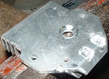
Then I used a drill and a Dremel tool to hog out some material from the bottom of the heat sink that Deve had supplied so the heat sink would sit flat on the regulator frame without interference from the rivets.
The next problem was that the module was just a little too big to fit inside the regulator cover. It would fit fine if the wire attachment tabs pointed up instead of out, so the tabs needed bending. I was afraid I might break something if I just tried bending them with no support, so I made this tool.
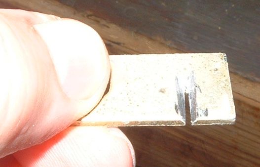
It is a piece of 1/8" steel with a slot cut in it using a hack saw. The slot was just wide enough to slide one of the tabs from the HEI module into. I used a Dremel tool to chamfer the slot out so the bend wouldn't be so abrupt. Here is the tool being used.
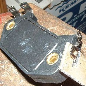
Here is the module mounted inside the regulator with all wires connected.
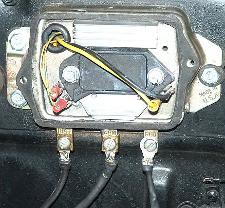
The BAT lug holds a shield with the actual +12 v lead (also connect to coil +) inside the shield and sneaking under the lug, up inside the regulator case to the "B" connection on the HEI module (large yellow wire). The ARM lug holds a shield for the black wire connected between HEI "C" connection and coil -. The FLD lug holds the shield for the twisted pair wires, small yellow to module W and yellow with blue stripe to G that come from the mag pickup in the distributor. All these wires are covered in black heat shrink tubing, making them look more or less like stock wiring and run up underneath the tabs so they are not obvious. Shielding the coil+ and coil- wires may be overkill, but it works for me.
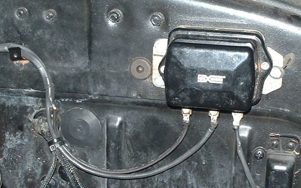
The end result:
Before I started I spent some time on the phone with Deve talking about mounting alternatives for the module, as I didn't want to use his mounting bracket. Nice guy, willing to help. Here is a pointer to his kit:
High Energy Ignition Using Your Stock Distributor!
I hooked up an old ignition scope that a friend gave me years ago. It showed that I had a total of about 6 degrees of timing jitter using my stock points distributor.
My first thought was to mount the HEI module inside the cab, but I was concerned with the 3-4 feet long leads from the mag pickup. The mag pickup voltage levels are very low and could be susceptible to electrical noise, especially over such long wires. My solution was to use shielded, 22 gauge, twisted pair wire from the pickup to the module.
Bilbo came by one day a couple of weeks ago and we went to work. The plan was to do a temporary installation with longer than necessary wires to assure that there wouldn't be problems with the final installation. We installed the HEI module on the passenger's side inner fender under the hood. We used 10' of the twisted pair wire for the pickup to HEI module, figuring that if that long wire worked OK, the final solution of 3-4 feet would work as well. We also shielded the 14 gauge wire we ran between the coil negative and the module to keep it from generating electrical noise into the mag pickup wire. Both shields were grounded at the HEI's ground point. Bilbo (an electrician by trade) pointed out that the shields should only be grounded at one end.
My GMC distributor was the "short cap" variety which does not have enough room inside to mount the mag pickup. Deve provided a "tall cap" distributor for an additional $30. It arrived freshly cleaned, painted and lubed and seemed to be in very good condition. Later testing with the HEI module showed the timing jitter of this distributor to be around 2.5 degrees total.
I have around 6000 miles (2 years) on my current set of plug wires, so I decided keep them. Same with the AC R45 spark plugs (nice light tan color on the inside insulators), so I just re-gapped them from the stock 0.032" to 0.045" and put them back in. Cranked up the engine, timed it to the BB, and then advanced it about 1/2 way to the "A" mark on the "octane selector" on the distributor. This engine started quickly using the stock ignition and so far it still does on the HEI.
Drove the truck for a week and a half using the temporary HEI mounting with the long wires and all seemed well. Mileage on the only tank of gas was 15.37 MPG, mostly suburban driving, which is slightly better than my usual 14.5 to 15 MPG, but hardly a good comparison with just one tankful used.
Up to this point I'd pretty much followed Deve's instructions with the exception of longer, shielded wires. In the mean time, I'd gone back and re-read his article. One thing I noticed was his comment about hiding the module inside an old voltage regulator cover. I decided to hide my module inside a voltage regulator, mounted in the stock location on the firewall. While I was at it, I'd disguise the wiring as best I could to make it look stock.
I started by removing all parts from the frame of the voltage regulator. Then I re-attached all three connection points to the frame using pop rivets.
The connection points (BAT, FLD and ARM) would be used later for ground points for wire shields.
Then I used a drill and a Dremel tool to hog out some material from the bottom of the heat sink that Deve had supplied so the heat sink would sit flat on the regulator frame without interference from the rivets.
The next problem was that the module was just a little too big to fit inside the regulator cover. It would fit fine if the wire attachment tabs pointed up instead of out, so the tabs needed bending. I was afraid I might break something if I just tried bending them with no support, so I made this tool.
It is a piece of 1/8" steel with a slot cut in it using a hack saw. The slot was just wide enough to slide one of the tabs from the HEI module into. I used a Dremel tool to chamfer the slot out so the bend wouldn't be so abrupt. Here is the tool being used.
Here is the module mounted inside the regulator with all wires connected.
The BAT lug holds a shield with the actual +12 v lead (also connect to coil +) inside the shield and sneaking under the lug, up inside the regulator case to the "B" connection on the HEI module (large yellow wire). The ARM lug holds a shield for the black wire connected between HEI "C" connection and coil -. The FLD lug holds the shield for the twisted pair wires, small yellow to module W and yellow with blue stripe to G that come from the mag pickup in the distributor. All these wires are covered in black heat shrink tubing, making them look more or less like stock wiring and run up underneath the tabs so they are not obvious. Shielding the coil+ and coil- wires may be overkill, but it works for me.
The end result:
") . Interesting reading . I am not that updated in electronically facts so its good to learn new topics to keep the little grey cells working ! Read your Hemmings article to Deve about " how to choose the best coil option" combined with the HEI system ?
. Interesting reading . I am not that updated in electronically facts so its good to learn new topics to keep the little grey cells working ! Read your Hemmings article to Deve about " how to choose the best coil option" combined with the HEI system ?